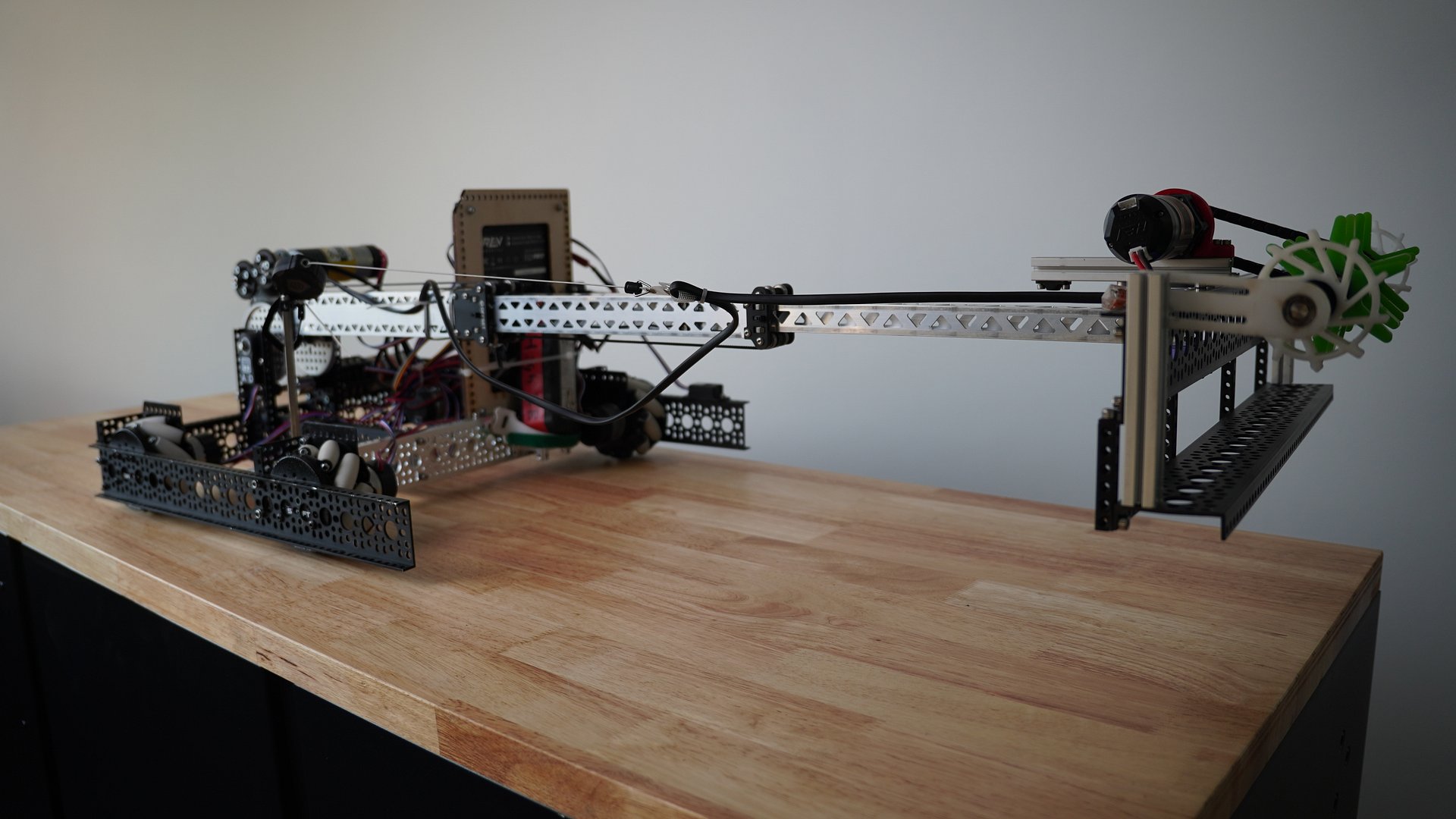
Pivoting Arm + Telescopic Elevator — Ball Collection Robot
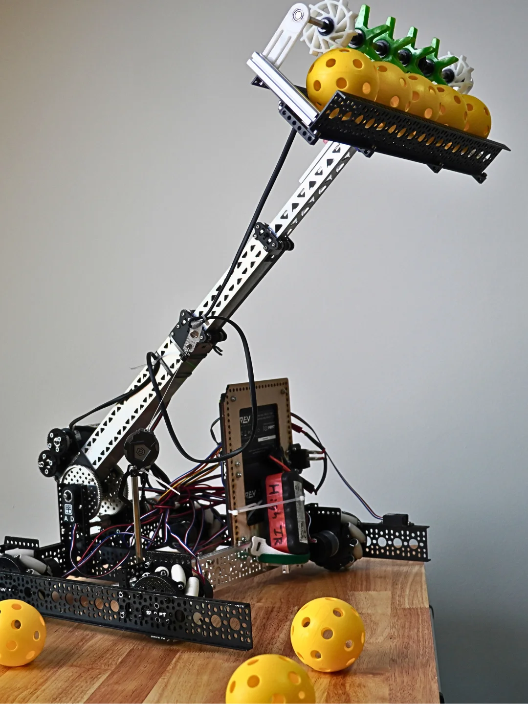
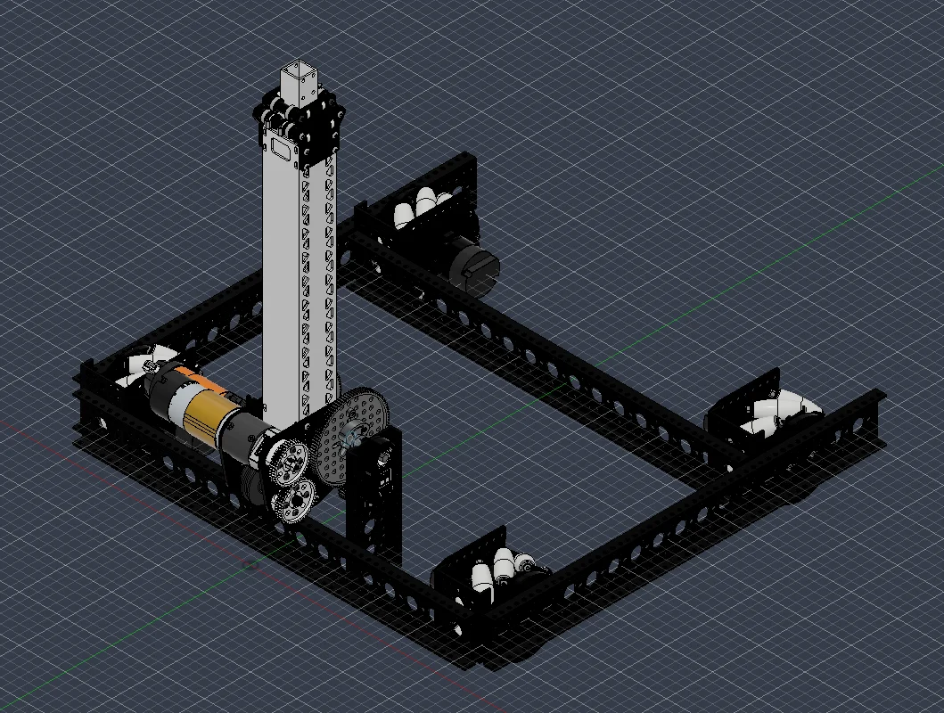
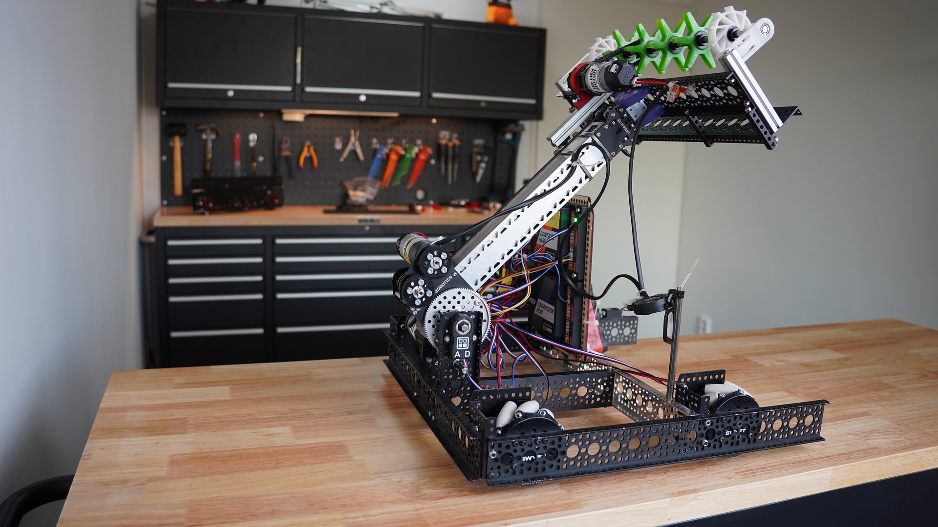
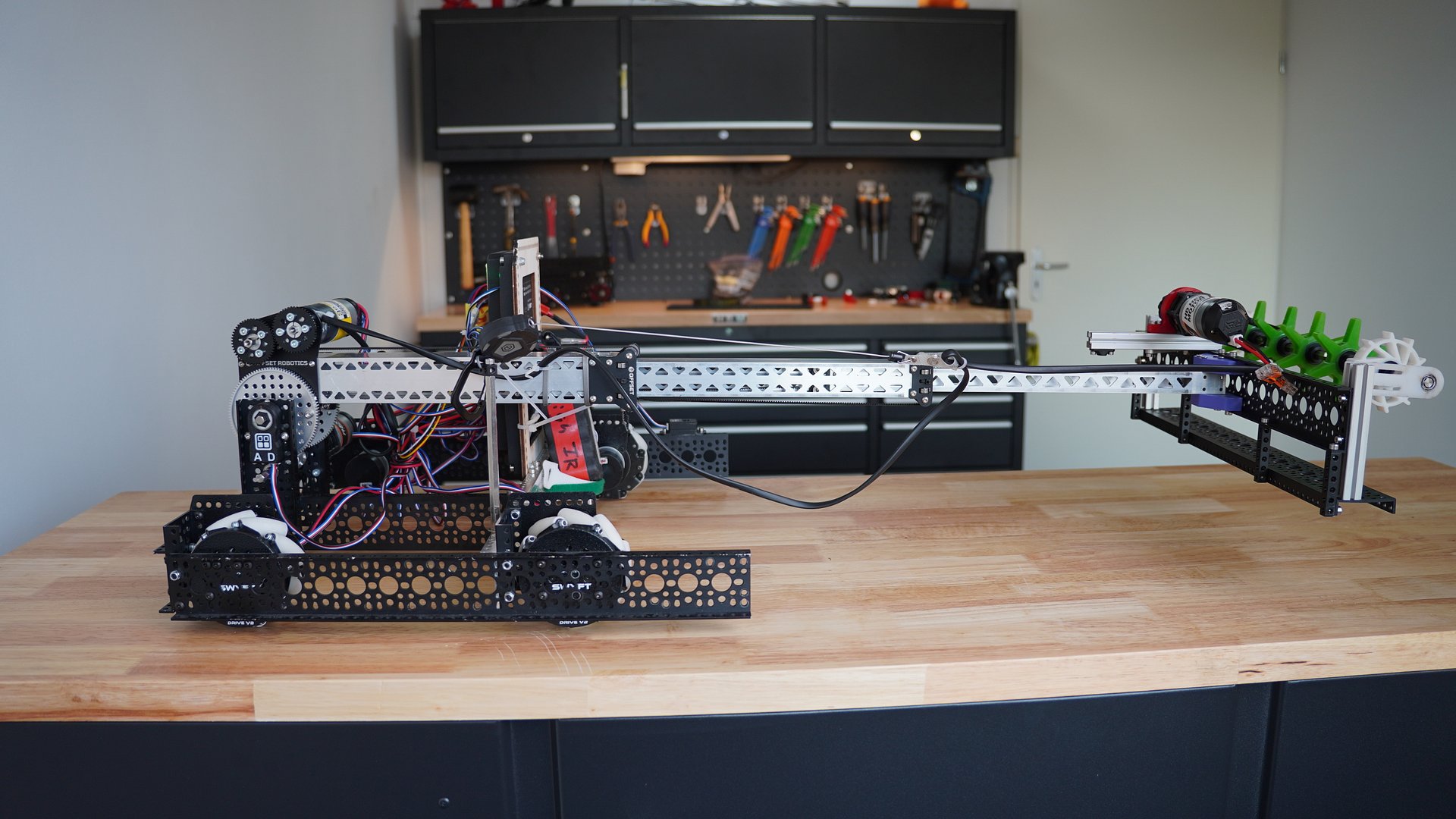
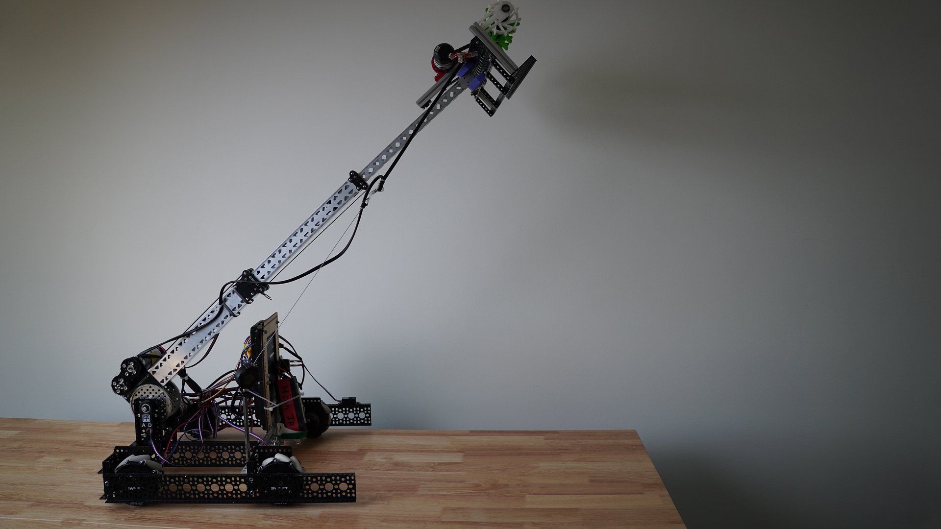
This is a full pivoting arm assembly built around a belt-driven telescopic box lift, designed to rotate down, extend out to pick up game elements, then rotate up to deposit at a different height. Great starting point for teams wanting a compact pick-and-place style mechanism instead of a traditional fixed-height slide.
The arm pivots on a single axis via a gear mounted at the base of the lift so the whole telescopic assembly swings through its rotation rather than staying vertical. At the end of the extended lift is an open space where you could place a variety of mechanisms, like this spinning intake roller setup to grab and hold onto ball-shaped game elements as the arm sweeps down to collect them. You can find intakes I've designed in the other products pages.
Note: this is not a finished, competition-ready mechanism — it's a starting reference for your team to build from and adapt to your own game/season needs.
- Telescopic lift structure is the Offset Robotics belt-driven box tube slide.
- Pivot mount uses a gear-driven rotation stage — you'll need to size your own motor/gearbox ratio depending on arm length and payload
- No electronics, limit switches, or homing sensors are included in this file — you'll want at least one for arm position feedback in a real build.
- No counterweighting strut mount or elastic tensioner is included, though if your arm is long/heavy you'll likely want one to reduce motor strain and allow a faster gear ratio.
Fair warning: the further you extend the lift while the arm is off-vertical, the more torque you need at the pivot. Plan your gear ratio accordingly rather than guessing.
Accessing STEP Files
STEP files are uploaded in a .zip folder. You must first unzip the folder in order to import the file into your CAD program of choice.
Autodesk Fusion 360
-
After unzipping the downloaded folder, open Fusion 360.
-
Click the "Show Data Panel" icon in the upper-left corner (it looks like a grid/waffle).
-
Navigate to your desired project and folder.
-
Click the "Upload" button.
-
Select the .step or .stp file from your computer and click "Open."
-
Once the upload is complete, the file will appear in your Data Panel, ready to be inserted into your design.
Onshape
-
After unzipping the downloaded folder, log in to your Onshape account.
-
From the "Documents" page, click the "Create" button and select "Import files...".
-
Alternatively, inside an existing document, click the "+" icon in the bottom-left corner and select "Import."
-
Select the .step or .stp file from your computer.
-
Choose your desired import options in the dialog box.
-
The imported file will appear as a new tab in your document.
SolidWorks
-
After unzipping the downloaded folder, open SolidWorks.
-
Go to "File" > "Open."
-
In the "Open" dialog box, change the file type to "STEP files (*.step, *.stp)."
-
Navigate to and select the STEP file you wish to import.
-
Click "Open."
-
SolidWorks may prompt you to run "Import Diagnostics" to check for and fix any potential issues with the imported geometry. It is recommended to do so.
3D Printing Tips
If the design includes 3D printed parts, I highly recommend you print the part out of PCTG. It has some of the highest impact resistance and non-catastrophic breaking for robot parts.
For Mechanical/structural parts, I recommend:
- 0.6mm Nozzles over 0.4mm. Wider nozzles produce stronger prints in shorter periods of time over thinner nozzles.
- Minimum 4 walls.
- 30-40% gyroid infill