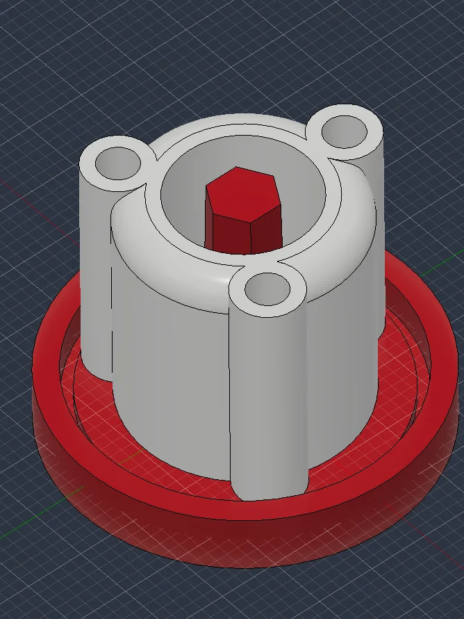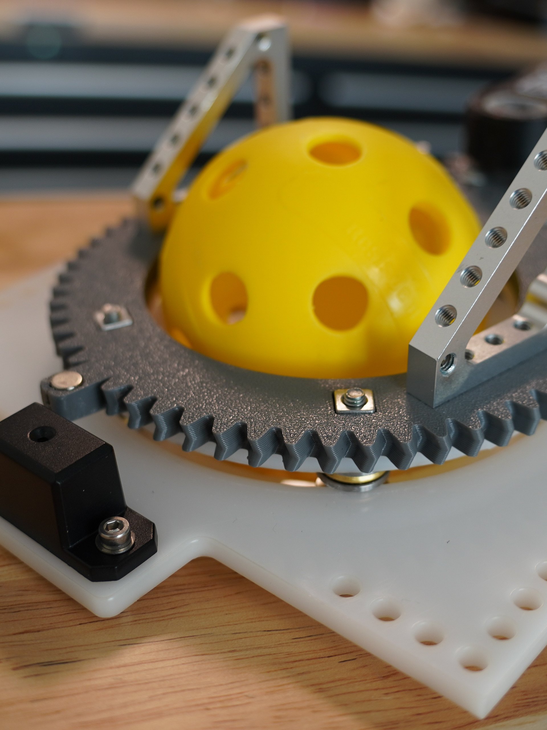
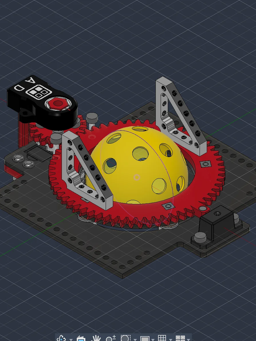
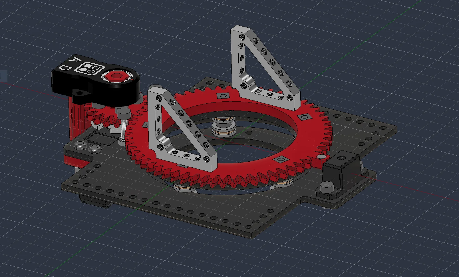
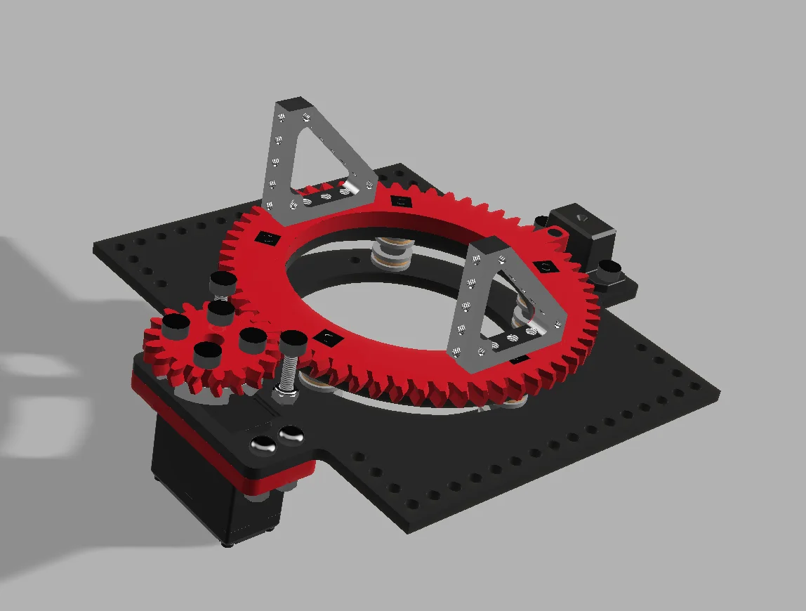
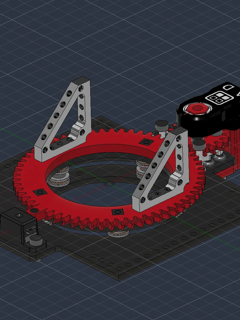
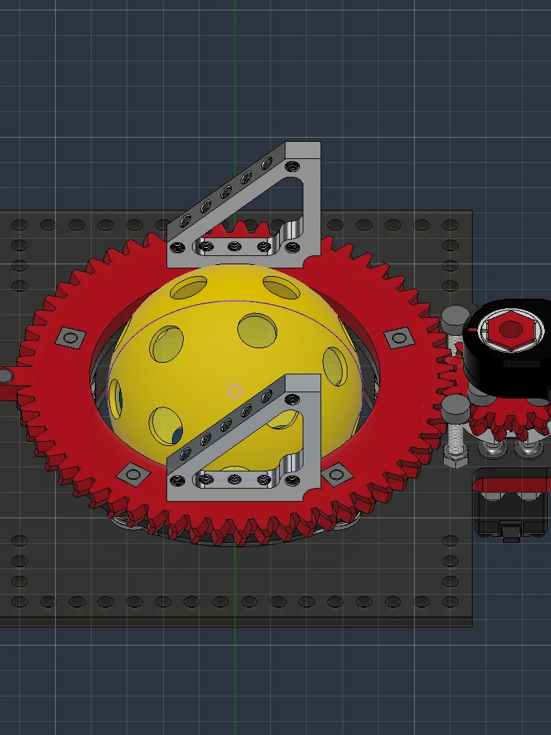
81mm ID Rotating Turret Base Kit: Thrust "Bearing Stack" Style
A rotating base for turrets, pan-and-tilt mounts, launchers, and swinging arms.
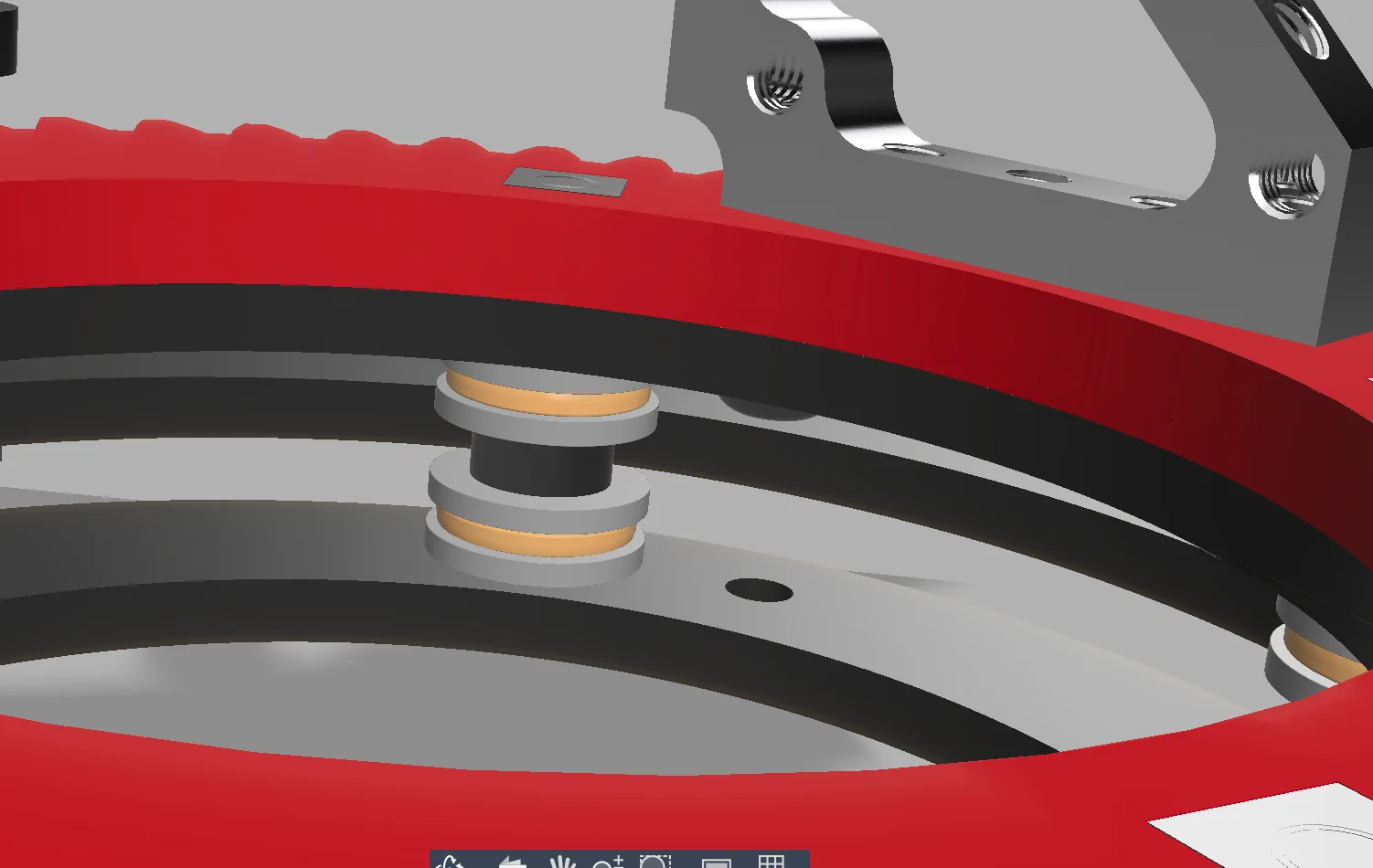
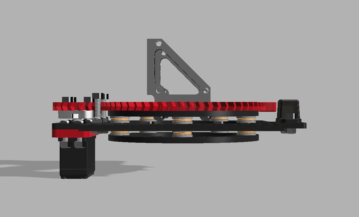
The ring gear opens to an 81mm inner diameter. A thrust bearing stack carries the ring, so it takes the radial load from the ring itself and the lateral push a flywheel or arm throws sideways. Swap the ring gear for a mounting plate, and the same bearings support a rotating arm just as well.
A physical stop limits rotation to about 340°~. You get most of a full turn without twisting wires past their limit. A servo drives the stock build. Swap in a DC motor, or run two servos together, with small changes to the mount.
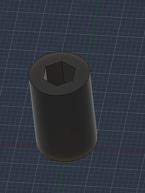
A magnetic limit switch zeros the turret at startup. Add the optional encoder mount, and a relative or absolute encoder tracks ring position. In relative mode, the limit switch can set your zero point every run if you so wish.
Built this for FTC's BIOBUZZ 26-27 season, but any build that needs a compact rotating platform can use it: camera mounts, sentry turrets, launcher heads, robotic arms.
Package includes STEP, 3MF, and DXF files, plus a full BOM.
Accessing STEP Files
STEP files are uploaded in a .zip folder. You must first unzip the folder in order to import the file into your CAD program of choice.
Autodesk Fusion 360
-
After unzipping the downloaded folder, open Fusion 360.
-
Click the "Show Data Panel" icon in the upper-left corner (it looks like a grid/waffle).
-
Navigate to your desired project and folder.
-
Click the "Upload" button.
-
Select the .step or .stp file from your computer and click "Open."
-
Once the upload is complete, the file will appear in your Data Panel, ready to be inserted into your design.
Onshape
-
After unzipping the downloaded folder, log in to your Onshape account.
-
From the "Documents" page, click the "Create" button and select "Import files...".
-
Alternatively, inside an existing document, click the "+" icon in the bottom-left corner and select "Import."
-
Select the .step or .stp file from your computer.
-
Choose your desired import options in the dialog box.
-
The imported file will appear as a new tab in your document.
SolidWorks
-
After unzipping the downloaded folder, open SolidWorks.
-
Go to "File" > "Open."
-
In the "Open" dialog box, change the file type to "STEP files (*.step, *.stp)."
-
Navigate to and select the STEP file you wish to import.
-
Click "Open."
-
SolidWorks may prompt you to run "Import Diagnostics" to check for and fix any potential issues with the imported geometry. It is recommended to do so.
3D Printing Tips
If the design includes 3D printed parts, I highly recommend you print the part out of PCTG. It has some of the highest impact resistance and non-catastrophic breaking for robot parts.
For Mechanical/structural parts, I recommend:
- 0.6mm Nozzles over 0.4mm. Wider nozzles produce stronger prints in shorter periods of time over thinner nozzles.
- Minimum 4 walls.
- 30-40% gyroid infill